
Golf Cart M12 Fan
Let’s ignore the delta between the last article post and this one. I’m building a FAN!
More precisely, I’m building a fan to keep myself cool during my attempts to drown my local golf course fish ecosystems with large white pellets. I got this idea when my Fiancee (Girlfriend at the time) and I were golfing and we were paired with two gentlemen that had Ryobi cup holder fans. I thought the concept of internal power tool system fan’s was great and about a month later got myself a M12 (I run red) Milwaukee portable fan.
The only documentation I could scour online for part references is the service parts list and the operator’s manual. Both of these don’t have callouts for the screws used on the sides as shown in the image below:
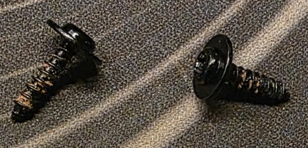
These fasteners as measured are T20, “M4” x 15mm Coarse Plastic-Forming black steel screws. McMaster “equivalent” would be 96817A329 screws paired with 92217A624 washers.
Additionally, there is some rubber rings that are used as a friction/dampening ring for the assembly.
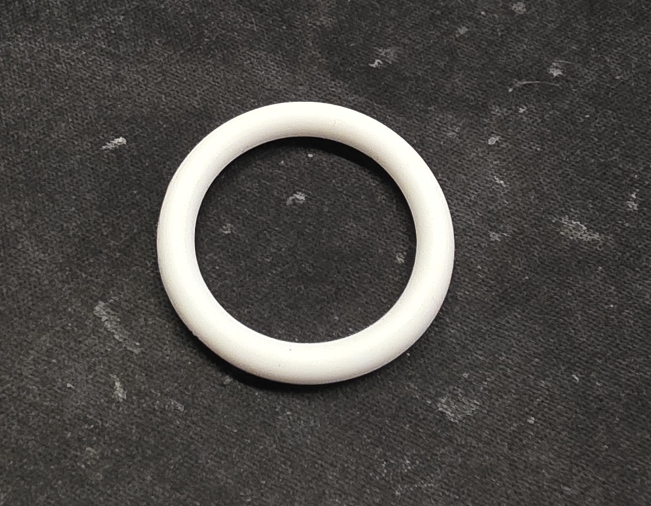
Measurements are 4.25mm cross section and 23.5mm ID, with a McMaster equivalent of 5233T816, although this PN is shy of the cross sectional diameter by 1mm (results should be similar, but beefing up the thickness on this can’t hurt).
V1
Anyways… The task here is simple - I want a M12 fan mount that stays in the inside of my golf cart. In order to do this I modeled the fan shape, of which there is some interesting geometry on the inside of the part.
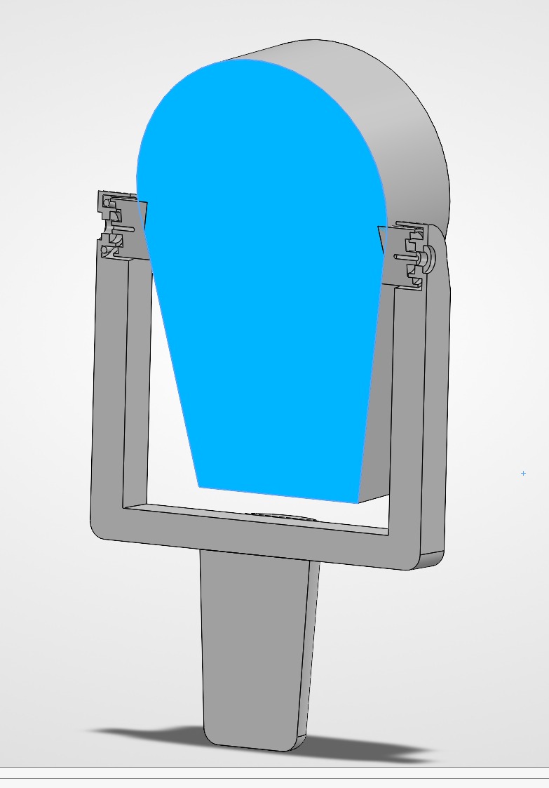
As shown above, if you take a look inside there is locating geometry that utilizes the friction ring to reduce movement of the fan if tilted. The rest of the design is self explanatory, where w.r.t. (with respect to) the ground rotation normal to the cupholder is unrestricted, as well as rotation perpendicular to the cupholder (axis made by side mounting screws). Additionally, I modled the clearance to be a bit forgiving so I can pack a beefier M12 battery. Time to print and assemble!
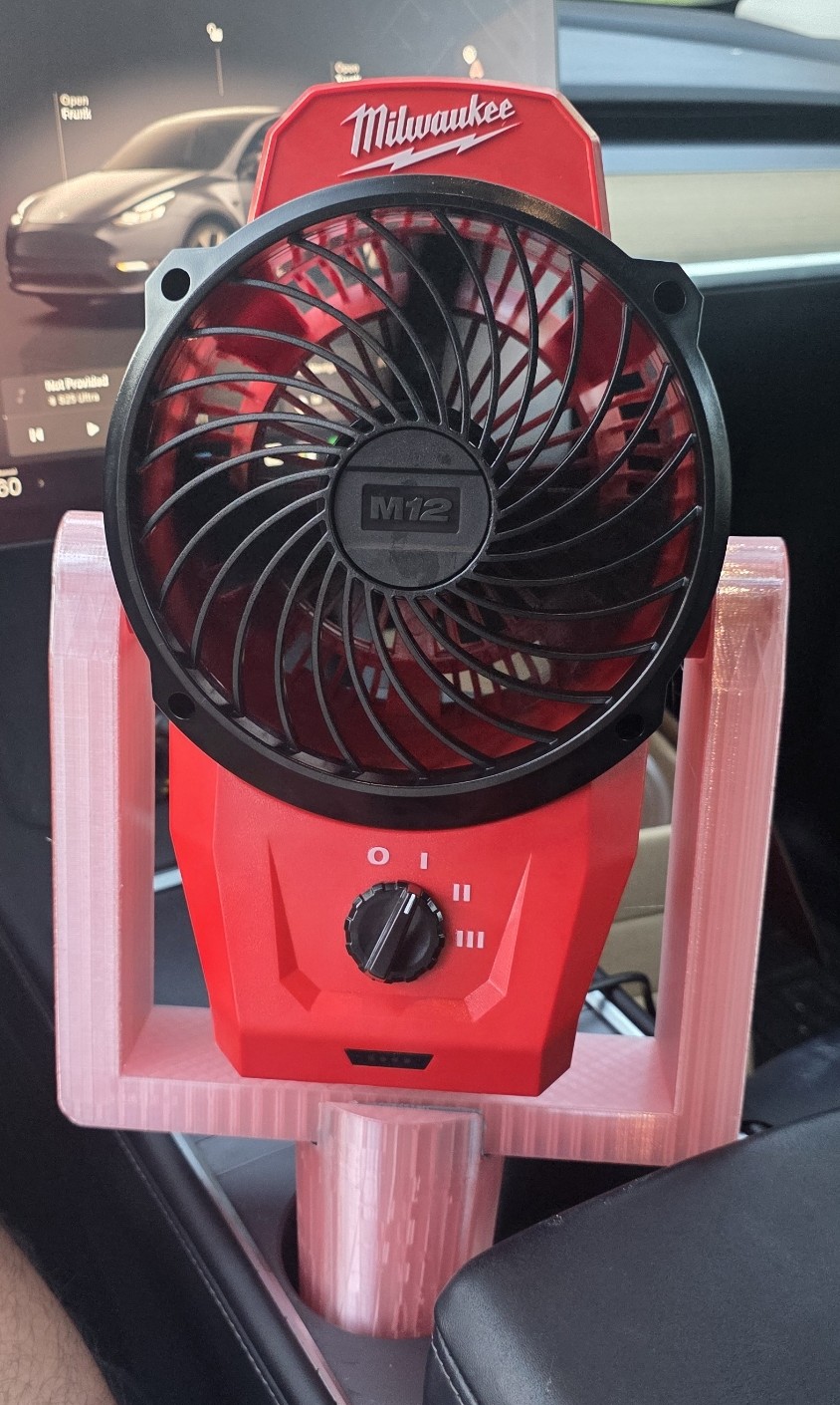
As shown above, this is the V1 fan (printed in two parts, where I just friction if the cupholder part to the bottom portion of the U bracket with some gorrila tape) inside my car to test the cupholder fit (more to come on this). Not bad… some notes on what to immediately fix though:
- reduce U length on sides by 4mm total
- reduce material consumed
- design improvements for DFM/DFA/DFP
V2
Back to the CAD, where I separated all the components for DFM/DFP (Design for Manufacturing and Design for Printing), utilizing M6 bolts and heat set inserts for DFA (Design for Assembly). Additionally, I reduced the material used and presto!
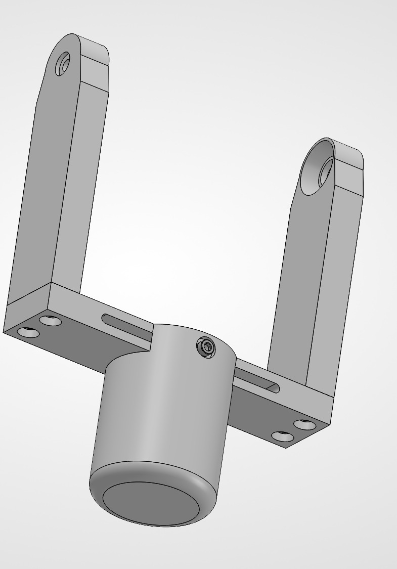
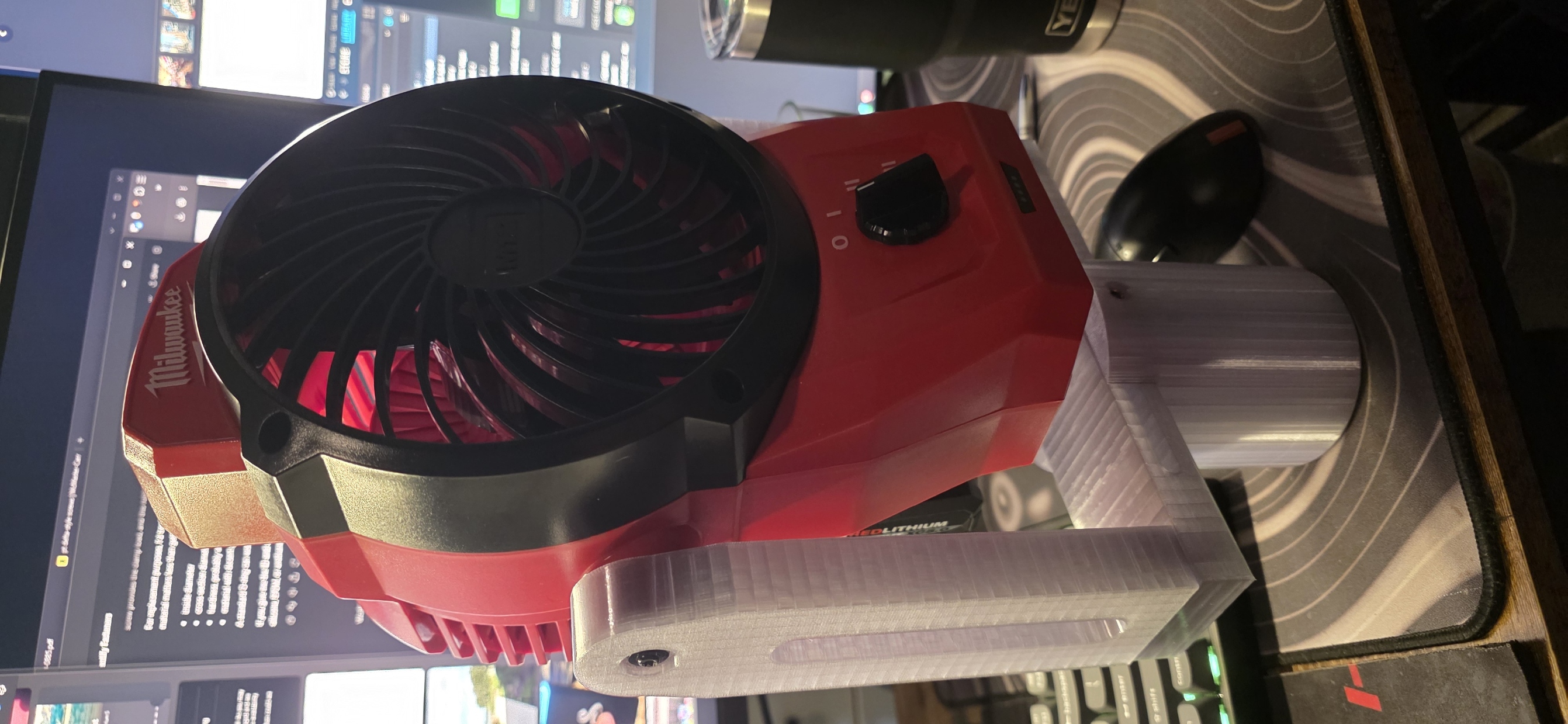
Now, we test on the golf course and I’ll report back here with my findings. Although, the next part of this will most definitely be handling the cupholder variances between carts.
V3
TBD…